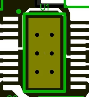
The bottom side is used primarily as a ground plane.
The LTC3265
The focal piece of my charge-pump control supply is the LTC3265 from Direct Tech/Simple Gadgets. It's accessible in two bundle styles: TSSOP and DFN. TSSOPs are little yet at any rate they have distending leads. I gathered this board myself and in the event that you intend to do likewise, I unquestionably prescribe the TSSOP.
As should be obvious, it has a warm cushion. Imperative: When an IC has this kind of uncovered (otherwise known as warm) cushion it is ordinarily a ground association, yet I would say, these ICs additionally have no less than one ground association among the typical pins. Subsequently, you might have the capacity to escape with not associating the presented cushion to ground (however I positively wouldn't prescribe this).
With the LTC3265, interestingly, the uncovered cushion is the main ground "stick," so you will have issues if there is anything but a decent association between the uncovered cushion and your ground hub. You can investigate the article Stencil Plan for Uncovered Cushion Bundles for some data on the most proficient method to guarantee that the uncovered cushion has an appropriate amount of bind glue.
As I neared the finish of my format, I understood that I had no helpful method to encase the warm cushion association in a huge copper region. Luckily, for my situation it didn't make a difference much since I have no compelling reason to work the load up at high temperatures, and subsequently I'm certain that I'll get a lot of warm alleviation from the six vias; these will exchange warm down to the ground plane on the base side of the load up. In the event that you have to expand warm exchange or if the base side of the load up isn't accessible, ensure that you abandon some vacant space close to the two shorter sides of the LTC3265 so you can broaden the warm cushion association out into some huge copper pours.
Inductance
My essential concern when I'm laying out an exchanging controller is inductance. Exchanging activity dependably prompts the nearness of high frequencies; regardless of whether the exchanging recurrence itself is fairly low, the fast on/off changes contain high-recurrence vitality.
More inductance implies all the more high-recurrence impedance, so inductance ought to be limited. The inductance of a PCB follow is relative to the length of the follow and contrarily corresponding to the width. In this manner, we lessen inductance (and opposition) by making short, wide follows. You can see two cases underneath. The main illustration is my format, and the second is the suggested design found in the datasheet.
Here is the schematic, with the goal that you can see which reference designators (in my format, not the datasheet's design) relate to which segments.
Assembling Contemplations
My arrangement was to collect this board utilizing patch glue and a hot-compressed air firearm. This is a minimal effort and generally simple approach to work with surface-mount parts, yet you need to prepare. On the off chance that I hope to collect a board by hand I attempt to abstain from anything littler than 0805. You'll additionally see that I have an average 0.1-inch header rather than the USB Miniaturized scale B impression. That is on the grounds that my Smaller scale B connector is really a breakout board. In the event that you intend to collect a PCB yourself and you require a Miniaturized scale B association, I very suggest this approach, in any event for the model stage.
I ordinarily utilize four-layer loads up in light of the fact that the execution is unrivaled and steering is significantly more straightforward, however for this situation, there is no requirement for four layers on the grounds that the directing isn't entangled and on the grounds that the load up requires just a ground plane (i.e., no power plane). Moreover, a two-layer board enables you to utilize OSH Stop's Super Quick administration, which as I would like to think is an astounding choice for ease, fast turn PCB creation.
I as of late found out about the presence of bismuth-based patch. This kind of bind is awesome for prototyping in light of the fact that it softens at a lower temperature—on account of the item that I utilized, 138°C, contrasted with ~183°C for leaded patch or ~220°C for average without lead weld. I utilized bismuth-based bind to gather the inductorless bipolar power supply, and everything I can state is that I will never return to the next stuff. The low softening point enabled me to amass the board with less warm weight on the segments (and less mental worry for myself), and revise was less demanding and quicker (and once more, less distressing).
Conclusion
I've just amassed and tried this charge-pump control supply, and I'm exceptionally satisfied with the outcomes (which will be distributed in an up and coming venture article). It's a direct and reduced arrangement; my PCB was just ~1.3 square inches. In the event that you think about this circuit as a subsystem that would be joined into a bigger PCB, and on the off chance that you take out the model just parts, it turns out to be significantly littler on the grounds that you could dispense with J1, C1, POT1, J2, J3, J4, and TP3– 5. This will end up being my go-to arrangement at whatever point I require symmetric rails for low-current simple or blended flag hardware.
| 


0 comments:
Post a Comment